MECH Capstone Project
2016-2017
-
Designed robotic arm end effector capable of pleating vacuum bag material, for use by DLR on large aerospace components.
-
Conducted extensive research and practiced infusion layups to come up with concept of operations.
-
Used Solidworks, 3d printer, and machine shop tools to design and manufacture 2 axis linear slide.
-
Responsible for writing most of and editing all of team’s technical documentation.
Background
Although I am an Integrated Engineering student, I had the opportunity to complete my fourth year capstone project through the Mechanical Engineering department when I was invited to join a project being solicited by DLR, the German aerospace agency. DLR and the UBC CARIS Lab were collaborating on automating labour-intensive aspects of manufacturing large composite aircraft and spacecraft parts using the vacuum infusion process. Our team of 5 engineering students was given the task of creating a proof of concept end effector able to automate the process of pleating the vacuum bag and positioning the pleat as desired on large composite parts. In short, we had to make a device to attach to the end of a robot arm capable of making and moving a pleat in plastic sheeting.
The Device
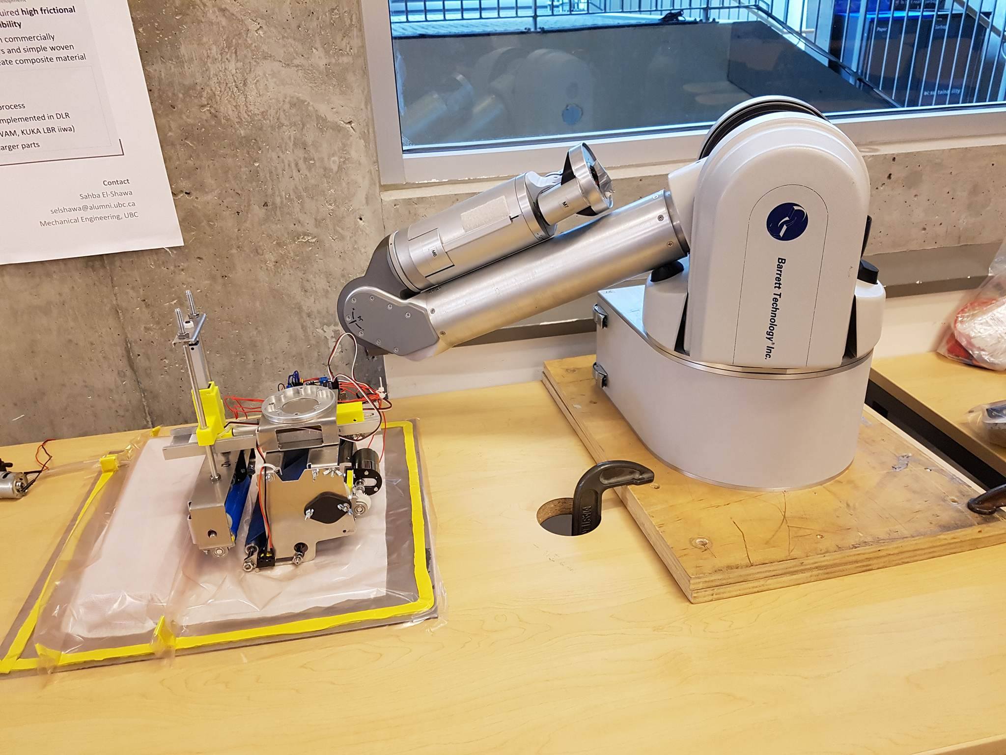
Our solution, called VIMEE, is an end effector with three main components: a wedge, an actuated composite belt, a roller system attached to an arm with two axes of freedom. The device is able to complete the pleating process in two steps: 1) gathering slack material using the wedge belt and 2) forming a pleat using both the wedge belt and the roller. Following the completion of the Capstone course, our clients at CARIS and DLR both expressed great interest for continuing the development of our prototype. The German Aerospace Center has also indicated their desire to improve and showcase our prototype at their annual conference in September.
Video showing VIMEE concept of operation.

My Work
My contributions were focused on three main aspects of the project, although I actively helped with nearly all aspects of the device’s design:
- Process Research and Concept of Operations Specification. I conducted extensive research into the vacuum infusion process, and led the team’s initial hands-on vacuum infusion simulations where we clarified and quantified the requirements for our device. I also developed the overall ‘strategy’ our device would use to form and move pleats through testing and practice forming and moving pleats with various shapes, methods, and materials. Video of one of our sessions.
- Design and Manufacture of the 2-axis actuation arm (Roller Arm) I was wholly responsible for the design of the actuation arm that gave the roller arm 2 axis freedom of motion.
- Editing of Technical Documentation I was responsible for final editing and submission of the large quantity of technical documentation required throughout the project. I wrote outlines for all major documents, assigned writing and other documentation work to other team members, and compiled and edited just over 250 pages worth of technical documentation over the course of the project.
Roller Arm
The roller arm was my main technical responsibity on the project. It had to actuate a powered roller in two axes over ~3”, and be able to apply at least 8lbsf in each axis. Further, our budget was very limited which meant most linear slides and actuators were not an option. The first number of weeks of the design process were spent testing and analyzing the process to determine the minimum stroke, force, and precision requirements for the actuation system.
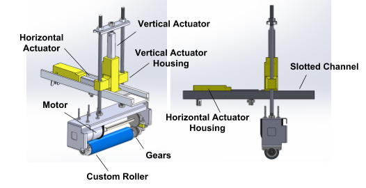
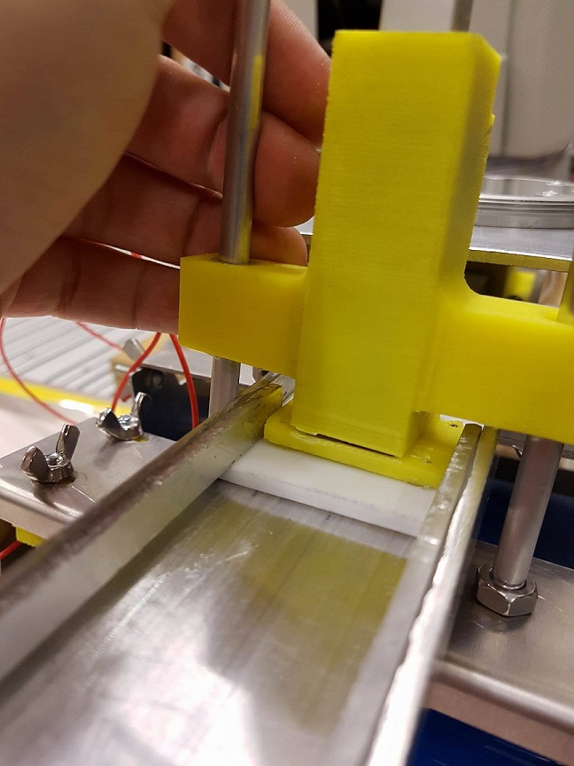
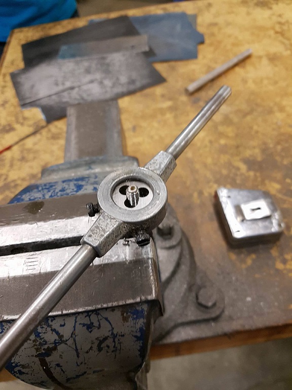
I selected two identical inexpensive linear actuators manufactured by Actuonix that had the required stroke length and force. For the horizontal slide, an aluminum U-channel was machined down to a low profile, and a vertical stop was epoxied onto the sides of the U to constrain the slide plate vertically. The slide plate was a machined rectangle of low-friction HDPE. The actuators were fixed to the slide plate and horizontal slide via 3d printed housings. For the vertical actuator connections, I waterjet and bent a piece of sheet metal that connected the vertical actuator to two aluminum rods, which I threaded for a secure connection.
Overall, the roller arm design met minimum requirements and came in under budget. I learned a lot about how to design parts that are easy to manufacture using shop tools and 3d printing, as well as ANSYS load analysis and Solidworks assembly management.
Pictures:
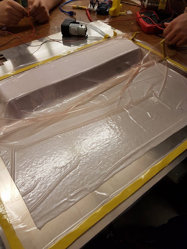
One of the early test setups
3d printing the actuator mounts
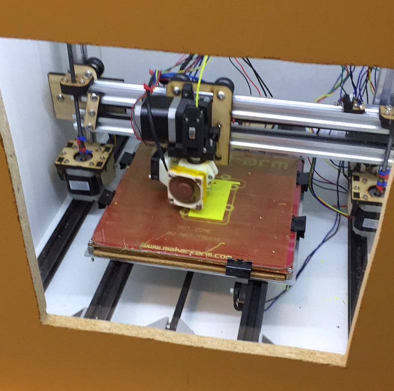
Early mounts were very brittle - stress concentrations were reduced in later iterations
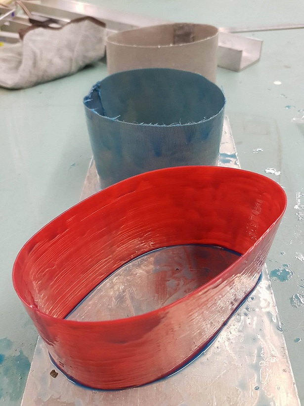
Casting the friction rollers using silicone reinforced with 3d printed nylon and fiberglass
Tapping one of the actuator rods
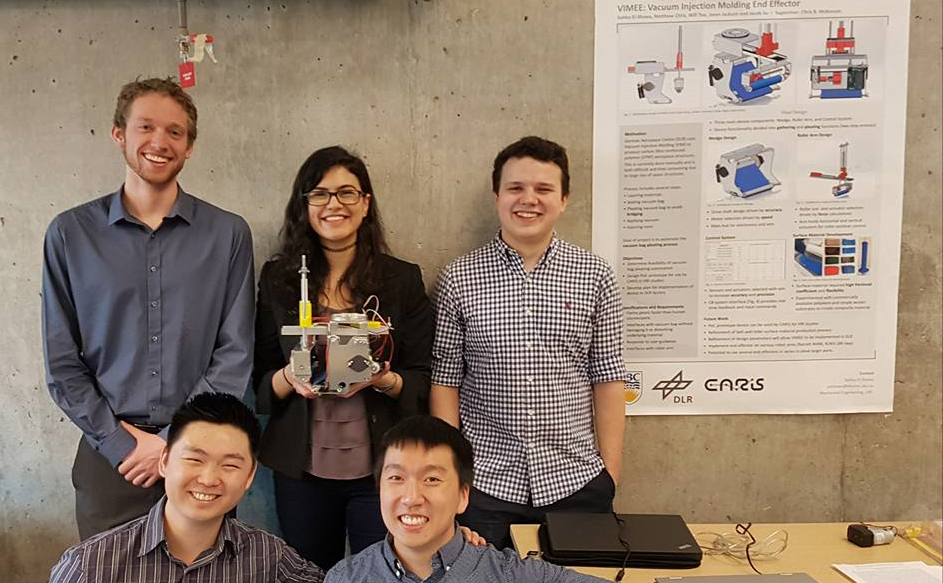
The team after demonstrating to DLR
